
Case Study – How to use Loconet turnouts in LCC Logic
The logic cells in the LCC nodes only work with items named with LCC names as defined by JMRI. That means you can only use a sensor with a MS prefix or a turnout with a MT prefix. That works fine when using LCC devices but if you want to use Loconet devices (turnouts) in your LCC Logic, that is a problem because Loconet turnout carry a LT prefix and there is no (current) device that will link Loconet directly to the LCC net which will allow LCC logic to use a LT named turnout. However, there is a workaround by using JMRI Logix to create a phantom LCC turnout (with correct MT prefix) that “follows” the Loconet turnout. Once this phantom LCC turnout has been created and is following the Loconet turnout, you can use the LCC turnout in an LCC logic the same as if it was a real LCC turnout. This allows you to use the phantom LCC turnout in LCC Logix to calculate items such as signal aspects.
NOTE – This requires that you have JMRI PanelPro operating and connected to your layout when operating. This restriction may be eliminated in the future when devices become available to establish a direct link between Loconet and the LCC net.
To create an LCC turnout (like a sensor), go to the CDI segment titled Sensor/Turnout creation. Insert the turnout name (be sure to use a MT prefix). In this example using LCC turnout #64L, the name would be MT64L. Two EventID’s are needed to create a System Name for this LCC turnout. Normally, when using real LCC turnouts, the turnout will have two EventID that represent the active and inactive state for the turnout. Those two EventID’s would then be used to create a turnout by inserting those two EventID’s in the Sensor/Turnout creation tool. Since we do not have a real LCC turnout in this case, we need to obtain those two events elsewhere as follows.
One option (free) is to obtain your own block of ID from the OpenLCB registry. This will give you a huge block of ID for your own use and they would be unique in the LCC world. You can then use those ID’s to create your own EventID’s that you can then use to create the phantom turnouts. If you are in a club, the club may have their own block of ID’s and can allocate some to you so you don’t need to register for your own block.
Once you have some EventID’s to use, go to the Sensor/Turnout creation form in the CDI. In the first field, insert an EventID to represent the “active” (thrown) turnout position and the second field will hold the EventID for the “inactive” (closed) turnout position. After created, the new LCC turnout MT64L will now show up in the JMRI turnout table with a System Name represented by the two EventID’s with a semicolon between them. The System Name will look like this MT05.01.01.01.3B.01.01.7E:05.01.01.3B.01.01.7F The active EventID is the first hex and the inactive is the second hex number with a semicolon between them.
Now that you have an LCC turnout MT64L, you can link it to the Loconet turnout (LT64L) you want it to follow. The image below shows a JMRI Logic that cause the phantom LCC turnout MT64L to follow the real Loconet turnout LT64L.
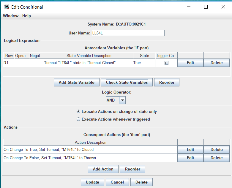
Figure 1- JMRI Logix to cause LCC turnout MT64L to follow Loconet turnout LT64L